
A thermocouple comprises an electrical circuit formed by two metal conductors of different metals soldered together at the ends. When there is a difference in temperature between the two joints, due to the Seebeck effect, a loop of current is generated and then, if one of the two joints is opened, an electromotive force (emf).
The polarization and intensity of the electromotive force depends solely on the type of metals used and the temperature to which the joints are subjected.
The joint exposed to the temperature to be measured is called the hot junction or the measuring junction while the joint between the thermocouple conductors and the measuring circuit is called the cold junction or the reference junction.
To measure a temperature with a thermocouple the reference junction must be at a given temperature (normally 0°) so that the emf generated depends solely on the temperature of the measuring junction. The type of thermocouple depends on the materials comprising the conductors which can be summarized as follows:
| Type | Temperature limits (°C) | Descriptions | |
|---|---|---|---|
| Symbol | Materials | ||
| S | Pt10%Rh - Pt | -50 / 1760 | Thermocouples composed of noble metals (Platinum and Rhodium) enable very precise measurements to be obtained. Especially resistant at high temperatures, it is generally used in oxidizing atmospheres. It is not really recommended in reducing atmospheres or those containing metal gases. |
| R | Pt13%Rh - Pt | -50 / 1760 | Like the "S" type thermocouple but with different percentages of the two metals. |
| B | Pt30%Rh - Pt6%Rh | 0 / 1820 | Thermocouple composed of noble metals which, due to a greater quantity of Rhodium than the "S" and "R" types, is more resistant at high temperatures and to mechanical stress. |
| E | Cr - Co | -270 / 1000 | Thermocouple with high thermoelectrical power which combines the positive pole of the "K" type thermocouple and the negative pole of the "J" type thermocouple. Particularly indicated in oxidizing atmospheres. |
| J | Fe - Co | -210 / 1200 | Thermocouple comprising an iron positive pole and a constantan (copper-nickel alloy) negative pole. Indicated for measuring medium temperatures in reducing atmospheres and with the presence of hydrogen and carbon. The presence of iron jeopardizes its working properly in oxidizing atmospheres. |
| K | Cr - Al | -270 / 1370 | Thermocouple composed of alloys containing nickel. It is suitable for measuring high temperatures in oxidizing atmospheres. Not to be used in reducing atmospheres. |
| T | Cu - Co | -270 / 400 | Thermocouple which permits accurate measurements at low temperatures in oxidizing and reducing atmospheres. |
| N | Nicrosil - Nisil | -270 / 400 (1) 0 / 1300 (2) |
Thermocouple for high temperatures similar to type "K" but with less hysteresis. |
| W3 | W3%Re- W25%Re | 0 / 2310 | Thermocouple for extremely high temperatures comprising a Tungsten positive pole containing 3% rhenium and a Tungsten negative pole containing 25% rhenium. Particularly resistant in reducing atmospheres and in the presence of hydrogen or other inert gases. Not to be used in air or oxidizing atmospheres. |
| W5 | W5%Re - W26%Re | 0 / 2310 | Thermocouple very similar to W3 but with a greater percentage of rhenium which increases its mechanical resistance. Other characteristics are identical to those of the W3 thermocouple. |
(1) Thermocouple with 0.32 mm diameter wires
(2) Thermocouple with 1.63 mm diameter wires
The methods for carrying out measurements with thermocouples can generally be divided into two types.
The first, as shown in figure No. 1, is generally used in industrial fields where extreme precision is not necessary
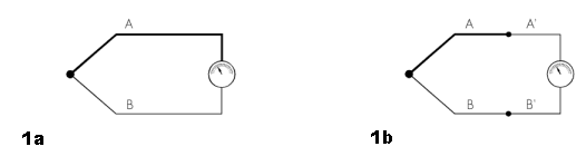
In this case the thermocouple is connected directly (fig. 1a) to the measuring device using compensated or extension cables (fig. 1b).
In this case the compensation of the reference junction is carried out directly by the measuring device which, measuring the junction temperature with other types of sensors, electronically modifies the thermocouple signal so that it is only dependent on the temperature of the measuring junction and thus the temperature to be measured.
The second type enables highly accurate measurements to be obtained and for this reason is used almost exclusively in laboratory applications.
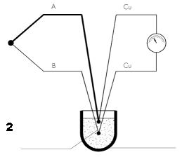
In this case the temperature of the reference junction is maintained at a given and constant temperature (normally the melting point of ice 0°C) through manual or automatic procedures in order to compensate the electromotive force measured by the measuring device with that corresponding to the measuring junction.
As in the case of resistance thermometers, there are also basically two construction types of thermocouples:
with traditional insulation and with mineral insulation.
The following table shows the main characteristics of the two construction types
| Response speed | Electrical Insulation | Resistance to vibrations | Resistance to pressure | |
|---|---|---|---|---|
| Traditional Insulation | Sufficient | Good | Sufficient | Good |
| Mineral Insulation (MgO) | Excellent | Good | Excellent | Excellent |
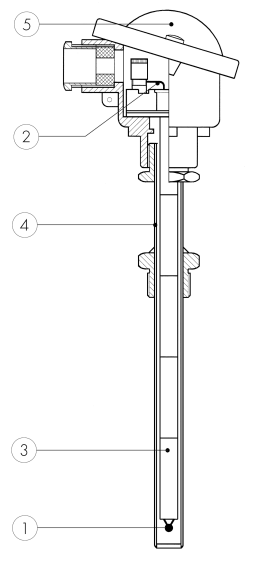
Traditional insulation thermocouples comprise:
In traditional insulation thermocouples the limits to the use of the different thermocouples is determined not only by the type of sheath but also by the dimensions of the thermocouple wires as indicated in the table below:
| TYPE | CONDITIONS | WIRE DIAMETER (mm) | |||||
|---|---|---|---|---|---|---|---|
| 3 | 1,5 | 1,3 | 0,8 | 0,5 | 0,25 | ||
| J | Bare wires | 650 | 480 | 480 | 425 | 340 | 310 |
| Sheated wires | 760 | 590 | 450 | 480 | 370 | 370 | |
| K/N | Bare wires | 1.090 | 925 | 925 | 870 | 760 | 700 |
| Sheated wires | 1.260 | 1.090 | 1.090 | 980 | 870 | 815 | |
| T | Bare wires | 315 | 315 | 260 | 200 | 200 | 200 |
| Sheated wires | 370 | 370 | 315 | 260 | 200 | 200 | |
| E | Bare wires | 760 | 590 | 590 | 480 | 370 | 370 |
| Sheated wires | 870 | 650 | 650 | 540 | 425 | 425 | |
| S/R | Bare wires | 1.540 | 1.480 | 1.320 | |||
| Sheated wires | |||||||
| B | Bare wires | 1.700 | |||||
| Sheated wires | |||||||
| Temperature limits in °C | |||||||
This particular construction type enables the production of high performance thermocouples with excellent mechanical characteristics. The made construction characteristics can be summarized as follows:
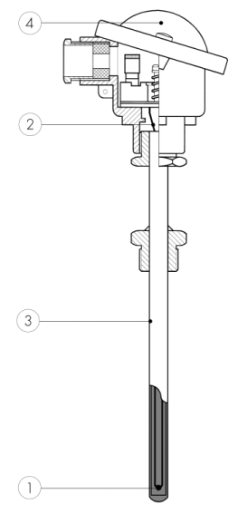
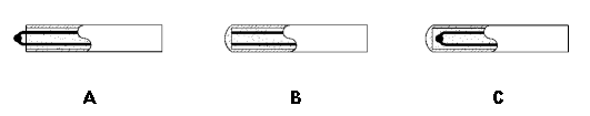
There are three types of measuring junction for mineral insulation thermocouples; the choice depends on the conditions of use of the thermocouple.
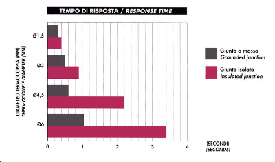
The following chart shows the time it takes a mineral insulation thermocouple to reach 63.2% of the thermal head measured in water with a speed of 0.4m/s
The main causes of errors which can occur while measuring the temperature with thermocouples are the following:
All the connections between the thermocouples and the measuring devices must be carried out with suitable compensated cables. There are compensated cables for each type of thermocouple, the choice of type of insulation and dimensions depends solely on the conditions of use (see section on cables).
All compensation and/or extension cables for thermocouples have a color identifying both the type of thermocouple and its polarity. It is, therefore, important to take care not to invert the polarities in any connections.
It is, however, good practice to make as few junctions as possible in connections between thermocouples and measuring instruments and to use the special devices with compensated contacts which prevent polarity inversion.
When using thermocouples with grounded measuring junctions, parasitic emf may be introduced from the thermocouple to the measuring device and, since the thermocouple signal is in mV, it may easily be disturbed or altered.
It is, therefore, advisable to use thermocouples with insulated measuring junctions.
As stated previously measuring with thermocouples requires the compensation of the reference junction; it is important that this be carried out correctly by the measuring device.
| °C | 0 | 10 | 20 | 30 | 40 | 50 | 60 | 70 | 80 | 90 | °C |
|---|---|---|---|---|---|---|---|---|---|---|---|
| FEM thermoelectric voltage in mV | |||||||||||
| 0 | 0,000 | -0,002 | -0,003 | -0,002 | 0,000 | 0,002 | 0,006 | 0,011 | 0,017 | 0,025 | 0 |
| 100 | 0,033 | 0,043 | 0,053 | 0,065 | 0,078 | 0,092 | 0,107 | 0,123 | 0,141 | 0,159 | 100 |
| 200 | 0,178 | 0,199 | 0,220 | 0,243 | 0,267 | 0,291 | 0,317 | 0,344 | 0,372 | 0,401 | 200 |
| 300 | 0,431 | 0,462 | 0,494 | 0,527 | 0,561 | 0,596 | 0,632 | 0,669 | 0,707 | 0,746 | 300 |
| 400 | 0,787 | 0,828 | 0,870 | 0,913 | 0,957 | 1,002 | 1,048 | 1,095 | 1,143 | 1,192 | 400 |
| 500 | 1,242 | 1,293 | 1,344 | 1,397 | 1,451 | 1,505 | 1,561 | 1,617 | 1,675 | 1,733 | 500 |
| 600 | 1,792 | 1,852 | 1,913 | 1,975 | 2,037 | 2,101 | 2,165 | 2,230 | 2,296 | 2,363 | 600 |
| 700 | 2,431 | 2,499 | 2,569 | 2,639 | 2,710 | 2,782 | 2,854 | 2,928 | 3,002 | 3,078 | 700 |
| 800 | 3,154 | 3,230 | 3,308 | 3,386 | 3,466 | 3,546 | 3,626 | 3,708 | 3,790 | 3,873 | 800 |
| 900 | 3,957 | 4,041 | 4,127 | 4,213 | 4,299 | 4,387 | 4,475 | 4,564 | 4,653 | 4,743 | 900 |
| 1.000 | 4,834 | 4,926 | 5,018 | 5,111 | 5,205 | 5,299 | 5,394 | 5,489 | 5,585 | 5,682 | 1.000 |
| 1.100 | 5,780 | 5,878 | 5,976 | 6,075 | 6,175 | 6,276 | 6,377 | 6,478 | 6,580 | 6,683 | 1.100 |
| 1.200 | 6,786 | 6,890 | 6,995 | 7,100 | 7,205 | 7,311 | 7,417 | 7,524 | 7,632 | 7,740 | 1.200 |
| 1.300 | 7,848 | 7,957 | 8,066 | 8,176 | 8,286 | 8,397 | 8,508 | 8,620 | 8,731 | 8,844 | 1.300 |
| 1.400 | 8,956 | 9,069 | 9,182 | 9,296 | 9,410 | 9,524 | 9,639 | 9,735 | 9,868 | 9,984 | 1.400 |
| 1.500 | 10,099 | 10,215 | 10,331 | 10,447 | 10,563 | 10,679 | 10,796 | 10,913 | 11,029 | 11,146 | 1.500 |
| 1.600 | 11,263 | 11,380 | 11,497 | 11,614 | 11,731 | 11,848 | 11,965 | 12,082 | 12,199 | 12,316 | 1.600 |
| 1.700 | 12,433 | 12,549 | 12,666 | 12,782 | 12,898 | 13,014 | 13,130 | 13,246 | 13,361 | 13,476 | 1.700 |
| 1.800 | 13,591 | 13,706 | 13,820 | 1.800 | |||||||
| °C | 0 | 10 | 20 | 30 | 40 | 50 | 60 | 70 | 80 | 90 | °C |
Reference junction at 0°C
| °C | 0 | -10 | -20 | -30 | -40 | -50 | -60 | -70 | -80 | -90 | °C |
|---|---|---|---|---|---|---|---|---|---|---|---|
| FEM thermoelectric voltage in mV | |||||||||||
| -200 | -8,825 | -9,063 | -9,274 | -9,455 | -9,604 | -9,718 | -9,797 | -9,835 | -200 | ||
| -100 | -5,237 | -5,681 | -6,107 | -6,516 | -6,907 | -7,279 | -7,632 | -7,963 | -8,273 | -8,561 | -100 |
| 0 | 0,000 | -0,582 | -1,152 | -1,709 | -2,255 | -2,787 | -3,306 | -3,381 | -4,302 | -4,777 | 0 |
| °C | 0 | 10 | 20 | 30 | 40 | 50 | 60 | 70 | 80 | 90 | °C |
|---|---|---|---|---|---|---|---|---|---|---|---|
| FEM thermoelectric voltage in mV | |||||||||||
| 0 | 0,000 | 0,591 | 1,192 | 1,801 | 2,420 | 3,048 | 3,685 | 4,330 | 4,985 | 5,648 | 0 |
| 100 | 6,319 | 6,998 | 7,685 | 8,379 | 9,081 | 9,789 | 10,503 | 11,224 | 11,951 | 12,684 | 100 |
| 200 | 13,421 | 14,164 | 14,912 | 15,664 | 16,420 | 17,181 | 17,945 | 18,713 | 19,484 | 20,259 | 200 |
| 300 | 21,036 | 21,817 | 22,600 | 23,386 | 24,174 | 24,964 | 25,757 | 26,552 | 27,348 | 28,146 | 300 |
| 400 | 28,946 | 29,747 | 30,550 | 31,354 | 32,159 | 32,965 | 33,772 | 34,579 | 35,387 | 36,196 | 400 |
| 500 | 37,005 | 37,815 | 38,624 | 39,434 | 40,243 | 41,053 | 41,862 | 42,671 | 43,479 | 44,286 | 500 |
| 600 | 45,093 | 45,900 | 46,705 | 47,509 | 48,313 | 49,116 | 49,917 | 50,718 | 51,517 | 52,315 | 600 |
| 700 | 53,112 | 53,908 | 54,703 | 55,497 | 56,289 | 57,080 | 57,870 | 58,659 | 59,446 | 60,232 | 700 |
| 800 | 61,017 | 61,801 | 62,583 | 63,364 | 64,144 | 64,922 | 65,698 | 66,473 | 67,246 | 68,017 | 800 |
| 900 | 68,787 | 69,554 | 70,319 | 71,082 | 71,844 | 72,603 | 73,360 | 74,115 | 74,869 | 75,621 | 900 |
| 1.000 | 76,373 | 1.000 | |||||||||
| °C | 0 | 10 | 20 | 30 | 40 | 50 | 60 | 70 | 80 | 90 | °C |
Reference junction at 0°C
| °C | 0 | -10 | -20 | -30 | -40 | -50 | -60 | -70 | -80 | -90 | °C |
|---|---|---|---|---|---|---|---|---|---|---|---|
| FEM thermoelectric voltage in mV | |||||||||||
| -200 | -7,890 | -8,095 | -200 | ||||||||
| -100 | -4,633 | -5,037 | -5,426 | -5,801 | -6,159 | -6,500 | -6,821 | -7,123 | -7,403 | -7,659 | -100 |
| 0 | 0,000 | -0,501 | -0,995 | -1,482 | -1,961 | -2,431 | -2,893 | -3,344 | -3,786 | -4,215 | 0 |
| °C | 0 | 10 | 20 | 30 | 40 | 50 | 60 | 70 | 80 | 90 | °C |
|---|---|---|---|---|---|---|---|---|---|---|---|
| FEM thermoelectric voltage in mV | |||||||||||
| 0 | 0,000 | 0,507 | 1,019 | 1,537 | 2,059 | 2,585 | 3,116 | 3,650 | 4,187 | 4,726 | 0 |
| 100 | 5,269 | 5,814 | 6,360 | 6,909 | 7,459 | 8,010 | 8,562 | 9,115 | 9,669 | 10,224 | 100 |
| 200 | 10,779 | 11,334 | 11,889 | 12,445 | 13,000 | 13,555 | 14,110 | 14,665 | 15,219 | 15,773 | 200 |
| 300 | 16,327 | 16,881 | 17,434 | 17,986 | 18,538 | 19,090 | 19,642 | 20,194 | 20,745 | 21,297 | 300 |
| 400 | 21,848 | 22,400 | 22,952 | 23,504 | 24,057 | 24,610 | 25,164 | 25,720 | 26,276 | 26,834 | 400 |
| 500 | 27,393 | 27,953 | 28,516 | 29,080 | 29,647 | 30,216 | 30,788 | 31,362 | 31,939 | 32,519 | 500 |
| 600 | 33,102 | 33,689 | 34,279 | 34,873 | 35,470 | 36,071 | 36,675 | 37,284 | 37,896 | 38,512 | 600 |
| 700 | 39,132 | 39,755 | 40,382 | 41,012 | 41,645 | 42,281 | 42,919 | 43,559 | 44,203 | 44,848 | 700 |
| 800 | 45,494 | 46,141 | 46,786 | 47,431 | 48,074 | 48,715 | 49,353 | 49,989 | 50,622 | 51,251 | 800 |
| 900 | 51,877 | 52,500 | 53,119 | 53,735 | 54,347 | 54,956 | 55,561 | 56,164 | 56,763 | 57,360 | 900 |
| 1.000 | 57,953 | 58,545 | 59,134 | 59,721 | 60,307 | 60,890 | 61,473 | 62,054 | 62,634 | 63,214 | 1.000 |
| 1.100 | 63,792 | 64,370 | 64,948 | 65,525 | 66,102 | 66,679 | 67,255 | 67,831 | 68,406 | 68,980 | 1.100 |
| 1.200 | 69,553 | 1.200 | |||||||||
| °C | 0 | 10 | 20 | 30 | 40 | 50 | 60 | 70 | 80 | 90 | °C |
Reference junction at 0°C
| °C | 0 | -10 | -20 | -30 | -40 | -50 | -60 | -70 | -80 | -90 | °C |
|---|---|---|---|---|---|---|---|---|---|---|---|
| FEM thermoelectric voltage in mV | |||||||||||
| -200 | -5,891 | -6,035 | -6,158 | -6,262 | -6,344 | -6,404 | -6,441 | -6,458 | -200 | ||
| -100 | -3,554 | -3,852 | -4,138 | -4,411 | -4,669 | -4,913 | -5,141 | -5,354 | -5,550 | -5,730 | -100 |
| 0 | 0,000 | -0,392 | -0,778 | -1,156 | -1,527 | -1,889 | -2,243 | -2,587 | -2,920 | -3,243 | 0 |
| °C | 0 | 10 | 20 | 30 | 40 | 50 | 60 | 70 | 80 | 90 | °C |
|---|---|---|---|---|---|---|---|---|---|---|---|
| FEM thermoelectric voltage in mV | |||||||||||
| 0 | 0,000 | 0,397 | 0,798 | 1,203 | 1,612 | 2,023 | 2,436 | 2,851 | 3,267 | 3,682 | 0 |
| 100 | 4,096 | 4,509 | 4,920 | 5,328 | 5,735 | 6,138 | 6,540 | 6,941 | 7,340 | 7,739 | 100 |
| 200 | 8,138 | 8,539 | 8,940 | 9,343 | 9,747 | 10,153 | 10,561 | 10,971 | 11,382 | 11,795 | 200 |
| 300 | 12,209 | 12,624 | 13,040 | 13,457 | 13,874 | 14,293 | 14,713 | 15,133 | 15,554 | 15,975 | 300 |
| 400 | 16,397 | 16,820 | 17,243 | 17,667 | 18,091 | 18,516 | 18,941 | 19,366 | 19,792 | 20,218 | 400 |
| 500 | 20,644 | 21,071 | 21,497 | 21,924 | 22,350 | 22,776 | 23,203 | 23,629 | 24,055 | 24,480 | 500 |
| 600 | 24,905 | 25,330 | 25,755 | 26,179 | 26,602 | 27,025 | 27,447 | 27,869 | 28,289 | 28,710 | 600 |
| 700 | 29,129 | 29,548 | 29,965 | 30,382 | 30,798 | 31,213 | 31,628 | 32,041 | 32,453 | 32,865 | 700 |
| 800 | 33,275 | 33,685 | 34,093 | 34,501 | 34,908 | 35,313 | 35,718 | 36,121 | 36,524 | 36,925 | 800 |
| 900 | 37,326 | 37,725 | 38,124 | 38,522 | 38,918 | 39,314 | 39,708 | 10,101 | 40,490 | 40,885 | 900 |
| 1.000 | 41,276 | 41,665 | 42,053 | 42,440 | 42,826 | 43,211 | 43,595 | 43,978 | 44,359 | 44,740 | 1.000 |
| 1.100 | 45,119 | 45,497 | 45,873 | 46,249 | 46,623 | 46,995 | 47,367 | 47,737 | 48,105 | 48,473 | 1.100 |
| 1.200 | 48,838 | 49,202 | 49,565 | 49,926 | 50,286 | 50,644 | 51,000 | 51,355 | 51,708 | 52,060 | 1.200 |
| 1.300 | 52,410 | 52,759 | 53,106 | 53,451 | 53,795 | 54,138 | 54,479 | 54,819 | 1.300 | ||
| °C | 0 | 10 | 20 | 30 | 40 | 50 | 60 | 70 | 80 | 90 | °C |
Reference junction at 0°C
| °C | 0 | -10 | -20 | -30 | -40 | -50 | -60 | -70 | -80 | -90 | °C |
|---|---|---|---|---|---|---|---|---|---|---|---|
| FEM thermoelectric voltage in mV | |||||||||||
| -200 | -3,990 | -4,083 | -4,162 | -4,226 | -4,313 | -4,336 | -4,345 | -200 | |||
| -100 | -2,407 | -2,612 | -2,808 | -2,994 | -3,171 | -3,336 | -3,491 | -3,634 | -3,766 | -3,884 | -100 |
| 0 | 0,000 | -0,260 | -0,518 | -0,772 | -1,023 | -1,269 | -1,509 | -1,744 | -1,972 | -2,193 | 0 |
| °C | 0 | 10 | 20 | 30 | 40 | 50 | 60 | 70 | 80 | 90 | °C |
|---|---|---|---|---|---|---|---|---|---|---|---|
| FEM thermoelectric voltage in mV | |||||||||||
| 0 | 0,000 | 0,261 | 0,525 | 0,793 | 1,065 | 1,340 | 1,619 | 1,902 | 2,189 | 2,480 | 0 |
| 100 | 2,774 | 3,072 | 3,374 | 3,680 | 3,989 | 4,302 | 4,618 | 4,937 | 5,259 | 5,585 | 100 |
| 200 | 5,913 | 6,245 | 6,579 | 6,916 | 7,255 | 7,597 | 7,941 | 8,288 | 8,637 | 8,988 | 200 |
| 300 | 9,341 | 9,696 | 10,054 | 10,413 | 10,774 | 11,136 | 11,501 | 11,867 | 12,234 | 12,603 | 300 |
| 400 | 12,974 | 13,346 | 13,719 | 14,094 | 14,469 | 14,846 | 15,225 | 15,604 | 15,984 | 16,366 | 400 |
| 500 | 16,748 | 17,131 | 17,515 | 17,900 | 18,286 | 18,672 | 19,059 | 19,447 | 19,835 | 20,224 | 500 |
| 600 | 20,613 | 21,003 | 21,393 | 21,784 | 22,175 | 22,566 | 22,958 | 23,350 | 23,742 | 24,134 | 600 |
| 700 | 24,527 | 24,919 | 25,312 | 25,705 | 26,098 | 26,491 | 26,883 | 27,276 | 27,669 | 28,062 | 700 |
| 800 | 28,455 | 28,847 | 29,239 | 29,632 | 30,024 | 30,416 | 30,807 | 31,199 | 31,590 | 31,981 | 800 |
| 900 | 32,371 | 32,761 | 33,151 | 33,541 | 33,930 | 34,319 | 34,707 | 35,095 | 35,482 | 35,869 | 900 |
| 1.000 | 36,256 | 36,641 | 37,027 | 37,411 | 37,795 | 38,179 | 38,562 | 38,944 | 39,326 | 39,706 | 1.000 |
| 1.100 | 40,087 | 40,466 | 40,845 | 41,223 | 41,600 | 41,976 | 42,352 | 42,727 | 43,101 | 43,474 | 1.100 |
| 1.200 | 43,846 | 44,218 | 44,588 | 44,958 | 45,326 | 45,694 | 46,606 | 46,425 | 46,789 | 47,152 | 1.200 |
| 1.300 | 47,513 | 1.300 | |||||||||
| °C | 0 | 10 | 20 | 30 | 40 | 50 | 60 | 70 | 80 | 90 | °C |
Reference junction at 0°C
| °C | 0 | -10 | -20 | -30 | -40 | -50 | -60 | -70 | -80 | -90 | °C |
|---|---|---|---|---|---|---|---|---|---|---|---|
| FEM thermoelectric voltage in mV | |||||||||||
| 0 | 0,000 | -0,051 | -0,100 | -0,145 | -0,188 | -0,226 | 0 | ||||
| °C | 0 | 10 | 20 | 30 | 40 | 50 | 60 | 70 | 80 | 90 | °C |
|---|---|---|---|---|---|---|---|---|---|---|---|
| FEM thermoelectric voltage in mV | |||||||||||
| 0 | 0,000 | 0,054 | 0,111 | 0,171 | 0,232 | 0,296 | 0,363 | 0,431 | 0,501 | 0,573 | 0 |
| 100 | 0,647 | 0,723 | 0,800 | 0,879 | 0,959 | 1,041 | 1,124 | 1,208 | 1,294 | 1,381 | 100 |
| 200 | 1,469 | 1,558 | 1,648 | 1,739 | 1,831 | 1,923 | 2,017 | 2,112 | 2,207 | 2,304 | 200 |
| 300 | 2,401 | 2,498 | 2,597 | 2,696 | 2,796 | 2,896 | 2,997 | 3,099 | 3,201 | 3,304 | 300 |
| 400 | 3,408 | 3,512 | 3,616 | 3,721 | 3,827 | 3,933 | 4,040 | 4,147 | 4,255 | 4,363 | 400 |
| 500 | 4,471 | 4,580 | 4,690 | 4,800 | 4,910 | 5,021 | 5,133 | 5,245 | 5,357 | 5,470 | 500 |
| 600 | 5,583 | 5,697 | 5,812 | 5,926 | 6,041 | 6,157 | 6,237 | 6,390 | 6,507 | 6,625 | 600 |
| 700 | 6,743 | 6,861 | 6,980 | 7,100 | 7,220 | 7,340 | 7,461 | 7,583 | 7,705 | 7,827 | 700 |
| 800 | 7,950 | 8,073 | 8,197 | 8,321 | 8,446 | 8,571 | 8,697 | 8,823 | 8,950 | 9,077 | 800 |
| 900 | 9,205 | 9,333 | 9,461 | 9,590 | 9,720 | 9,850 | 9,980 | 10,111 | 10,242 | 10,374 | 900 |
| 1.000 | 10,506 | 10,638 | 10,771 | 10,905 | 11,039 | 11,173 | 11,307 | 11,442 | 11,578 | 11,714 | 1.000 |
| 1.100 | 11,850 | 11,986 | 12,123 | 12,260 | 12,397 | 12,535 | 12,673 | 12,812 | 12,950 | 13,089 | 1.100 |
| 1.200 | 13,228 | 13,367 | 13,507 | 13,646 | 13,786 | 13,926 | 14,066 | 14,207 | 14,347 | 14,488 | 1.200 |
| 1.300 | 14,629 | 14,770 | 14,911 | 15,052 | 15,193 | 15,334 | 15,475 | 15,616 | 15,758 | 15,899 | 1.300 |
| 1.400 | 16,040 | 16,181 | 16,323 | 16,464 | 16,605 | 16,746 | 16,887 | 17,028 | 17,169 | 17,310 | 1.400 |
| 1.500 | 17,451 | 17,591 | 17,732 | 17,872 | 18,012 | 18,152 | 18,292 | 18,431 | 18,571 | 18,710 | 1.500 |
| 1.600 | 18,849 | 18,988 | 19,126 | 19,264 | 19,402 | 19,540 | 19,677 | 19,814 | 19,951 | 20,087 | 1.600 |
| 1.700 | 20,222 | 20,356 | 20,488 | 20,620 | 20,749 | 20,877 | 21,003 | 1.700 | |||
| °C | 0 | 10 | 20 | 30 | 40 | 50 | 60 | 70 | 80 | 90 | °C |
Reference junction at 0°C
| °C | 0 | -10 | -20 | -30 | -40 | -50 | -60 | -70 | -80 | -90 | °C |
|---|---|---|---|---|---|---|---|---|---|---|---|
| FEM thermoelectric voltage in mV | |||||||||||
| 0 | 0,000 | -0,053 | -0,103 | -0,150 | -0,194 | -0,236 | 0 | ||||
| °C | 0 | 10 | 20 | 30 | 40 | 50 | 60 | 70 | 80 | 90 | °C |
|---|---|---|---|---|---|---|---|---|---|---|---|
| FEM thermoelectric voltage in mV | |||||||||||
| 0 | 0,000 | 0,055 | 0,113 | 0,173 | 0,235 | 0,299 | 0,365 | 0,433 | 0,502 | 0,573 | 0 |
| 100 | 0,646 | 0,720 | 0,795 | 0,872 | 0,950 | 1,029 | 1,110 | 1,191 | 1,273 | 1,357 | 100 |
| 200 | 1,441 | 1,526 | 1,612 | 1,698 | 1,786 | 1,874 | 1,962 | 2,052 | 2,141 | 2,232 | 200 |
| 300 | 2,323 | 2,415 | 2,507 | 2,599 | 2,692 | 2,786 | 2,880 | 2,974 | 3,096 | 3,164 | 300 |
| 400 | 3,259 | 3,355 | 3,451 | 3,548 | 3,645 | 3,742 | 3,840 | 3,938 | 4,036 | 3,134 | 400 |
| 500 | 4,233 | 4,332 | 4,432 | 4,532 | 4,632 | 4,732 | 4,833 | 4,934 | 5,035 | 5,137 | 500 |
| 600 | 5,239 | 5,341 | 5,443 | 5,546 | 5,659 | 5,753 | 5,857 | 5,961 | 6,065 | 6,170 | 600 |
| 700 | 6,275 | 6,381 | 6,486 | 6,593 | 6,699 | 6,806 | 6,913 | 7,020 | 7,128 | 7,236 | 700 |
| 800 | 7,345 | 7,454 | 7,563 | 7,673 | 7,783 | 7,893 | 8,003 | 8,114 | 8,226 | 8,337 | 800 |
| 900 | 8,449 | 8,562 | 8,674 | 8,787 | 8,900 | 9,014 | 9,128 | 9,242 | 9,357 | 9,472 | 900 |
| 1.000 | 9,587 | 9,703 | 9,819 | 9,935 | 10,051 | 10,168 | 10,285 | 10,403 | 10,520 | 10,638 | 1.000 |
| 1.100 | 10,757 | 10,875 | 10,994 | 11,113 | 11,232 | 11,351 | 11,471 | 11,590 | 11,710 | 11,830 | 1.100 |
| 1.200 | 11,951 | 12,071 | 12,191 | 12,312 | 12,433 | 12,554 | 12,675 | 12,796 | 12,917 | 13,038 | 1.200 |
| 1.300 | 13,159 | 13,280 | 13,402 | 13,523 | 13,644 | 13,766 | 13,887 | 14,009 | 14,130 | 14,251 | 1.300 |
| 1.400 | 14,373 | 14,494 | 14,615 | 14,736 | 14,857 | 14,978 | 15,099 | 15,220 | 15,341 | 15,461 | 1.400 |
| 1.500 | 15,582 | 15,702 | 15,822 | 15,942 | 16,062 | 16,182 | 16,301 | 16,420 | 16,539 | 16,658 | 1.500 |
| 1.600 | 16,777 | 16,895 | 17,013 | 17,131 | 17,249 | 17,366 | 17,483 | 17,600 | 17,717 | 17,832 | 1.600 |
| 1.700 | 17,947 | 18,061 | 18,174 | 18,825 | 18,395 | 18,503 | 18,609 | 1.700 | |||
| °C | 0 | 10 | 20 | 30 | 40 | 50 | 60 | 70 | 80 | 90 | °C |
Reference junction at 0°C
| °C | 0 | -10 | -20 | -30 | -40 | -50 | -60 | -70 | -80 | -90 | °C |
|---|---|---|---|---|---|---|---|---|---|---|---|
| FEM thermoelectric voltage in mV | |||||||||||
| -200 | -5,603 | -5,753 | -5,888 | -6,007 | -6,105 | -6,180 | -6,232 | -6,258 | -200 | ||
| -100 | -3,379 | -3,657 | -3,923 | -4,177 | -4,419 | -4,648 | -4,865 | -5,070 | -5,261 | -5,439 | -100 |
| 0 | 0,000 | -0,383 | -0,757 | -1,121 | -1,475 | -1,819 | -2,153 | -2,476 | -2,788 | -3,089 | 0 |
| °C | 0 | 10 | 20 | 30 | 40 | 50 | 60 | 70 | 80 | 90 | °C |
|---|---|---|---|---|---|---|---|---|---|---|---|
| FEM thermoelectric voltage in mV | |||||||||||
| 0 | 0,000 | 0,391 | 0,790 | 1,196 | 1,612 | 2,036 | 2,468 | 2,909 | 3,358 | 3,814 | 0 |
| 100 | 4,279 | 4,750 | 5,228 | 5,714 | 6,206 | 6,704 | 7,209 | 7,720 | 8,237 | 8,759 | 100 |
| 200 | 9,288 | 9,822 | 10,362 | 10,907 | 11,458 | 12,013 | 12,574 | 13,139 | 13,709 | 14,283 | 200 |
| 300 | 14,862 | 15,445 | 16,032 | 16,624 | 17,219 | 17,819 | 18,422 | 19,030 | 19,641 | 20,255 | 300 |
| 400 | 20,872 | 400 | |||||||||
Reference junction at 0°C
| TYPE | JIS C 1602 | ANSI MC 96.1 | DIN 43710 | EN 60584-2 | |||||||
|---|---|---|---|---|---|---|---|---|---|---|---|
| Temp. range (°C) | Grade | Tolerance (°C) | Temp. range (°C) | Grade | Tolerance (°C) | Temp. range (°C) | Tolerance (°C) | Temp. range (°C) | Grade | Tolerance (°C) | |
| B | +200+1700 | 0.5 | ± 4°C or ± 0.5% | +800+1700 | STD | ± 0.5% | - | - | +600+1700 | 2 | ± 0.0025*|t| |
| 3 | ± 4°C or ± 0.005* |t| | ||||||||||
| R | 0+1600 | 0.25 | ± 1.5°C or ± 0.25% | 0+1450 | STD | ± 1,5°C or ± 0,25% | 0+600 | ± 3°C | 0-1600 | 1 | ± 1°C or ± [1+0.003 * (T-1100)]°C |
| SPC | ± 0,6°C or ± 0,1% | +600+1600 | ± 5°C | 2 | ± 1,5°C or ± 0.0025 * |t| | ||||||
| S | 0+1600 | 0.25 | ± 1.5°C or ± 0.25% | 0+1450 | STD | ± 1,5°C or ± 0,25% | 0-600 | ± 3°C | 0-1600 | 1 | ± 1°C or ± [1+0.003 * (T-1100)]°C |
| SPC | ± 0,6°C or ± 0,1% | 600-1600 | ± 5°C | 2 | ± 1,5°C or ± 0.0025* |t| | ||||||
| K | 0+1000 | 0.4 | ± 1.5°C or ± 0.4% | 0+1250 | STD | ± 2.2°C or ± 0.75% | 0+400 | ± 3°C | -40+1000 | 1 | ± 1,5°C or ± 0.004* |t| |
| 400+1200 | ± 0.75°C | ||||||||||
| 0+1200 | 0.75 | ± 2.5°C or ± 0.75% | SPC | ± 1.1°C or ± 0.40% | -40+1200 | 2 | ± 2,5°C or ± 0.0075* |t| | ||||
| -200-0 | 1.5 | ± 2.5°C or ± 1.5% | -200-0 | STD | ± 2.2°C or ± 2% | -200+40 | 3 | ± 2,5°C or ± 0.015* |t| | |||
| N | 0+1000 | 0.25 | ± 1.5°C or ± 0.4% | 0+1250 | STD | ± 2.2°C or ± 0.75% | - | - | -40+1000 | 1 | ± 1,5°C or ± 0.004* |t| |
| 0+1200 | 0.75 | ± 2.5°C or ± 0.75% | SPC | ± 1.1°C or ± 0.40% | -40+1200 | 2 | ± 2,5°C or ± 0.0075* |t| | ||||
| -200-0 | 1.5 | ± 2.5°C or ± 1.5% | -200-0 | STD | ± 2.2°C or ± 2% | -200+40 | 3 | ± 2,5°C or ± 0.015* |t| | |||
| E | 0+800 | 0.4 | ± 1.5°C or ± 0.4% | 0+900 | STD | ± 1,7°C or ± 0.50% | - | - | -40-800 | 1 | ± 1,5°C or ± 0.004* |t| |
| 0.75 | ± 2.5°C or ± 0.75% | SPC | ± 1°C or ± 0.40% | -40-900 | 2 | ± 2,5°C or ± 0.0075* |t| | |||||
| -200-0 | 1.5 | ± 2.5°C or ± 1.5% | -200-0 | STD | ± 1.7°C or ± 1% | -200-40 | 3 | ± 2,5°C or ± 0.015* |t| | |||
| J | 0+750 | 0.4 | ± 1.5°C or ± 0.4% | 0+750 | STD | ± 2.2°C or ± 0.75% | 0.400 | ± 3°C | -40+750 | 1 | ± 1,5°C or ± 0.004* |t| |
| 0.75 | ± 2.5°C or ± 0.75% | SPC | ± 1.1°C or ± 0.4% | 400+900 | ± 0.75° | 2 | ± 2,5°C or ± 0.0075* |t| | ||||
| T | 0+350 | 0.4 | ± 0.5°C or ± 0.4% | 0+350 | STD | ± 0.5°C or ± 0.4% | -200+400 | ± 3°C | -40+350 | 1 | ± 0,5°C or ± 0.004* |t| |
| 0.75 | ± 1°C or ± 0.75% | SPC | ± 1°C or ± 0.75% | 2 | ± 1°C or ± 0.0075* |t| | ||||||
| -200-0 | 1.5 | ± 1°C or ± 1.5% | -200-0 | STD | ± 1°C or ± 1.5% | -200+40 | 3 | ± 1°C or ± 0.015* |t| | |||